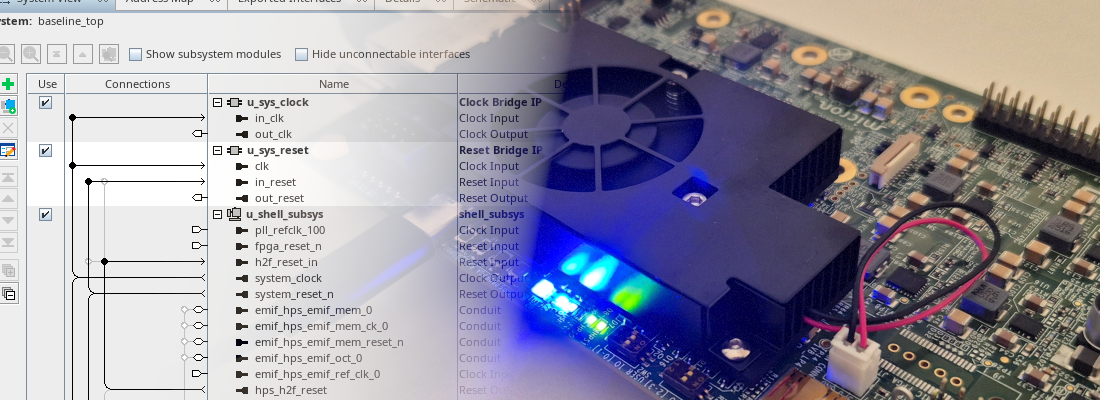
Running Linux on the Agilex 3 HPS and adding a custom IP to the fabric
 Altera Agilex 3 FPGA and SoC C-Series Development Kit
Another season starts! And there is no better way to begin this new season than diving into the Agilex 3 SoC and exploring its capabilities. In the first article about the Agilex 3 dev kit, I focused on the part that, for me, was the most interesting: the FPGA and its floating-point capabilities. Today we are going to be software developers for a bit, and we are going to take a look at the Hard Processor System (HPS) side of the board.
In this article, first we are going to take a look at the Golden System Reference Design (GSRD) for the Agilex 3 SoC, understand its structure, and then proceed to add a custom IP to the FPGA fabric. Initially my idea was to write only one article covering the custom IP and the Linux driver, but this turned out to be too much for a single post, so I decided to split it into two parts. This first part will focus on the hardware side, and the follow-up will cover the software integration.
Table of contents
- Booting the GSRD image
- What is inside the golden design
- Adding a custom IP to the fabric
- Conclusions
Booting the GSRD image
The fastest way to get Linux running on the HPS is the prebuilt SD card image that is published on RocketBoards. The file you want is sdimage.tar.gz, and it goes to the SD card with balenaEtcher or dd, nothing special.
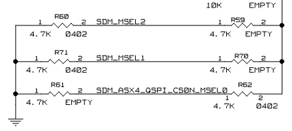
What is not obvious is that flashing the SD card is only half of the job. If you look at the board schematics, the MSEL[0..2] pins are strapped so the device always boots from the QSPI flash (the same that we have with the KR260) The SD card is never the first thing the Secure Device Manager looks at: the SDM loads the configuration and the first stage bootloader from QSPI, and only then does the boot chain jump to the SD card to find U-Boot and the kernel.
On a factory board that QSPI is empty, so the board does nothing at all until you program it. On the same RocketBoards directory, you will find the file ghrd.hps.jic. This file is the one that needs to be written into the QSPI flash to make the board boot correctly.
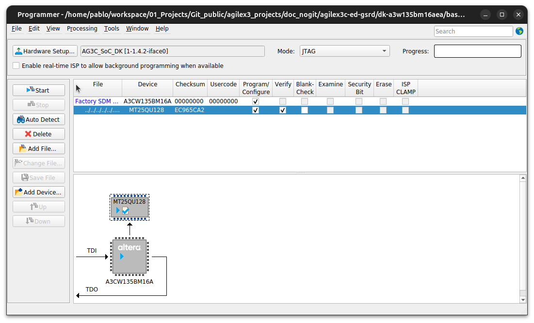
With the QSPI programmed and the SD card in the slot, powering the board gives you a Poky login on the serial console:
agilex3 login: root

WARNING: Poky is a reference Yocto Project distribution that should be used for
testing and development purposes only. It is recommended that you create your
own distribution for production use.

root@agilex3:~#
The image is more complete than I expected for a reference distribution. There is a native gcc and a Python 3.12 interpreter on the target, so you can compile and script directly on the board without setting up a cross-toolchain for quick experiments:
root@agilex3:~# python3
Python 3.12.12 (main, Oct  9 2025, 11:07:00) [GCC 13.4.0] on linux
Type "help", "copyright", "credits" or "license" for more information.
>>> exit()
What is inside the golden design
Booting the official image is fine as a smoke test, but this is an SOC, so we can add custom IP to the fabric. To do that, you need to understand what that image expects from the fabric. The hardware part of the GSRD lives in the agilex3c-ed-gsrd repository, under dk-a3w135bm16aea/baseline, and the way to read it is to open the project in Quartus Prime Pro and then open baseline_top.qsys in Platform Designer.
The first impression is that the design is very hierarchical. Almost nothing is instantiated at the top level; everything is wrapped in subsystems, and you have to descend a couple of levels to find the peripherals.
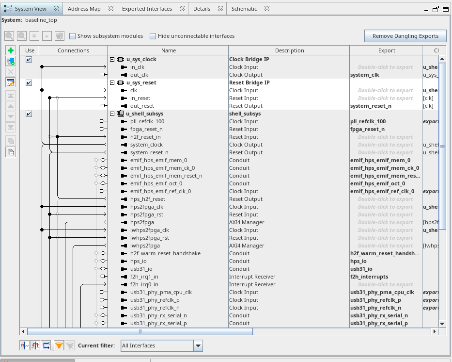
The path that matters for anything we want to add is the lightweight bridge. The AXI interface coming out of the HPS lands on lwh2f_axi_bridge, and the output of that bridge feeds u_peripherals_mm_bridge, which is an Avalon Memory Mapped Pipeline Bridge. Notice that we go from AXI to Avalon there: Platform Designer inserts the protocol adaptation logic automatically, so an Avalon-MM slave is directly reachable from a Linux mmap on the Cortex-A55 side. That is the hook I used for my own peripheral.
Adding a custom IP to the fabric
Because the SD card image was built for Quartus Prime Pro 26.1, the new design has to be built with the same version. This is not a recommendation, it is a hard requirement — the bitstream on the card and the one you produce have to agree on a set of hashes, which is a story for the next article. So the starting point is the GSRD repository at the matching tag:
git clone https://github.com/altera-fpga/agilex3c-ed-gsrd
cd agilex3c-ed-gsrd/
git checkout QPDS26.1_REL_GSRD_PR
From there the rule is simple: modify the fabric as much as you like, but do not touch the HPS configuration and do not touch the I/O. The HPS pin mux and the EMIF settings are frozen by what is already programmed in QSPI, and the FPGA I/O ring is fixed by the bitstream the bootloader loads at startup. Changing either one means rebuilding the boot chain, and the board will not come back up if you get it wrong.
The peripheral I wrote is avalon_matrix_mult, a square matrix multiplier with an Avalon-MM slave interface. It is a simple hardware — one multiply-accumulate per clock cycle over the shared k index, with the operand and result matrices held in register arrays — because the interesting part of this article is the plumbing, not the arithmetic. The register map is four control words followed by three windows, and both the RTL and the Platform Designer description file are in the GitHub repository under hps_custom_ip/:
localparam [7:0] ADDR_ID = 8'd0; /* identification register, read only */
localparam [7:0] ADDR_CTRL = 8'd1; /* writing bit 0 starts a multiplication */
localparam [7:0] ADDR_STATUS = 8'd2; /* bit 0 busy, bit 1 done */
localparam [7:0] ADDR_SIZE = 8'd3; /* matrix order, lets software discover the geometry */
localparam [7:0] CTRL_WORDS = 8'd16; /* words reserved for the control block */
localparam [31:0] ID_VALUE = 32'h4D4D554C; /* ascii "MMUL", lets software confirm the ip is mapped */
The ID and SIZE registers are not decoration. ID is how software proves the peripheral is really mapped where it thinks it is, and SIZE exposes the matrix_size parameter so that rebuilding the IP with a different order needs no change on the software side.
The component description file
Writing the RTL is the easy part. What cost me an afternoon and a conversation with Sonnet and even Opus participate, is that adding a .v file to the Quartus project does not make the IP appear in Platform Designer. These are two independent mechanisms: a VERILOG_FILE assignment in the .qsf makes the module visible to synthesis, while Platform Designer builds its IP Catalog by scanning the IP search path for _hw.tcl files. No _hw.tcl, no entry in the catalog.
The GSRD already declares a search path, so anything dropped under custom_ip/ is picked up:
set_global_assignment -name IP_SEARCH_PATHS "custom_ip/**/*"
The description file needs the module identity, a fileset pointing at the source, the parameters, and the interfaces:
package require -exact qsys 25.3.1

set_module_property NAME avalon_matrix_mult
set_module_property DISPLAY_NAME avalon_matrix_mult
set_module_property GROUP "Custom IP"
set_module_property VERSION 1.0
set_module_property EDITABLE true

add_fileset QUARTUS_SYNTH QUARTUS_SYNTH generate_fileset
set_fileset_property QUARTUS_SYNTH TOP_LEVEL avalon_matrix_mult

proc generate_fileset {entity_name} {
  add_fileset_file avalon_matrix_mult.v VERILOG PATH ../../../../../hps_custom_ip/rtl/avalon_matrix_mult.v TOP_LEVEL_FILE
}

add_parameter matrix_size INTEGER 4
set_parameter_property matrix_size DISPLAY_NAME "Matrix order"
set_parameter_property matrix_size ALLOWED_RANGES {2:8}
set_parameter_property matrix_size HDL_PARAMETER true

add_interface clock clock end
add_interface_port clock aclk clk Input 1

add_interface reset reset end
set_interface_property reset associatedClock clock
set_interface_property reset synchronousEdges DEASSERT
add_interface_port reset aresetn reset_n Input 1

add_interface avs_s0 avalon end
set_interface_property avs_s0 associatedClock clock
set_interface_property avs_s0 associatedReset reset
set_interface_property avs_s0 addressUnits WORDS
set_interface_property avs_s0 readLatency 1
add_interface_port avs_s0 avs_address address Input 8
add_interface_port avs_s0 avs_read read Input 1
add_interface_port avs_s0 avs_readdata readdata Output 32
add_interface_port avs_s0 avs_write write Input 1
add_interface_port avs_s0 avs_writedata writedata Input 32
The PATH is resolved relative to the _hw.tcl file itself. I point it back at my own repository instead of copying the .v into the GSRD tree, so there is a single source of truth for the RTL.
Two of those interface properties deserve to be understood rather than copied. addressUnits WORDS means avs_address is a word address: the interconnect drops the two low bits of the byte address (because each word uses 4 bytes), so word 16 in the RTL is byte offset 0x40 as seen from the HPS. And readLatency 1 is because of the interconnect samples readdata exactly one cycle after asserting read, which is what registering the read in an always @(posedge aclk) gives you. Add a pipeline stage later and forget to bump this number, and reads silently return the previous word.
Everything else is optional.
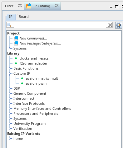
With the file in place, File > Refresh System makes the component show up under Custom IP, ready to be dropped into u_fabric_subsys.
Assigning the base address by hand
Once the peripheral is connected — clock and reset to the domain that feeds u_peripherals_mm_bridge, and avs_s0 to a master port of that bridge — it needs a base address, and this is less automatic than it should be.
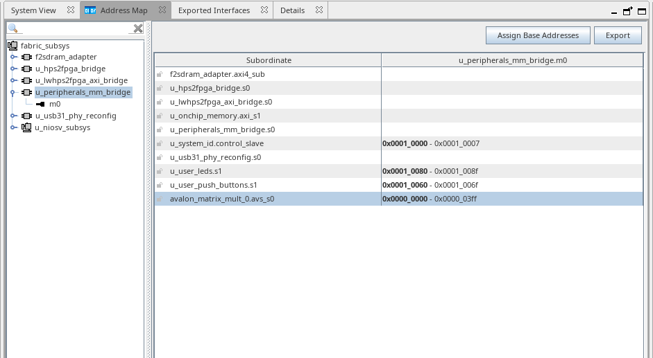
The GSRD peripherals live from 0x0001_0000 upwards, but a newly added IP lands at 0x0000_0000. My instinct was to reach for the Assign Base Addresses button, and that is exactly what you should not do: it reassigns all the addresses in the system, so every Linux driver or userspace tool that already hardcodes a peripheral address stops working.
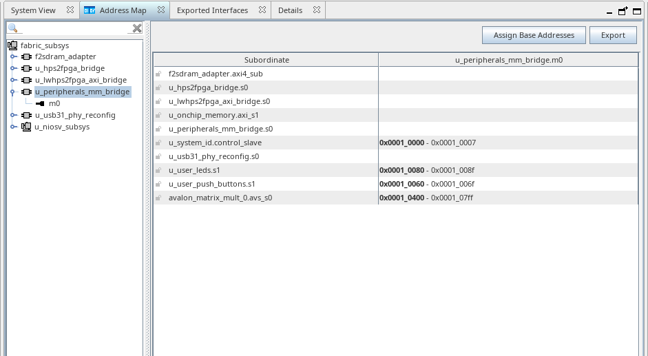
I assigned the address manually to 0x0001_0400, past the existing peripherals. Keep in mind that this is the address inside the fabric subsystem: from the HPS side an offset is added, so the system address ends up being 0x2001_0400. That is the number software will use.
At this point we just need to generate the bitstream and the .rbf file, that will be the file used to reconfigure the FPGA fabric from Linux.
Conclusions
At this point, we have a hardware design based on the GSRD for the Agilex 3 SoC, with our custom IP integrated into the FPGA fabric, which, honestly, is the easy part. The next article will dive into the software side, and how we can reconfigure the fabric from Linux while it is running, and how it keeps running correctly after the reconfiguration.
I have contradictory feelings about Platform Designer: it is cleaner than a diagram, but in some aspects it feels like it is hiding too much of what is going on under the hood. In any case, it is a different approach and, if you are more comfortable with diagrams, you can also use the Visual Designer Studio (VDS). Regarding the Agilex 3, I still think that it is a very interesting part of the SoC ecosystem, and exploring it further is definitely worthwhile.