Implementing AES-128 in Verilog: ECB core and CTR wrapper

Usually when we hear about cryptography we think about Bitcoin, NSA and NVIDIA GPUs, but cryptography is much more than that, and it is a key part of our cybersecurity. Unlike digital signal processing algorithms or control systems, cryptographic algorithms are designed from a very digital perspective, and, unlike most people often think, they are not software algorithms, they are hardware algorithms.
For this reason, they are a perfect fit for FPGAs, and in this article, I want to show you how to implement one of the most used symmetric encryption algorithms, the AES-128, in Verilog. We will start with the implementation of the AES-128 core in ECB mode, and then we will create a wrapper to use it in CTR mode.
Table of contents
- Symmetric encryption and block ciphers
- AES-128, AES-192, and AES-256
- AES block structure and byte ordering
- AES key expansion
- AES Electronic Codebook (ECB) mode
- AES Counter (CTR) mode
- Conclusion
Symmetric encryption and block ciphers
Symmetric encryption means that the same secret key is used for both encryption and decryption. The sender and receiver must both know this key and keep it private. The security of the scheme depends on protecting that secret and on the cryptographic strength of the algorithm.
A block cipher is a symmetric algorithm that operates on fixed-size blocks of data. AES is the most common modern standard in this category. Regardless of key length variant, AES processes data in 128-bit blocks. This means plaintext streams must be segmented into 16-byte blocks and then transformed block by block, either directly (for ECB) or through an operation mode (CTR, CBC, GCM, etc.).
In hardware, block ciphers are a great fit because they are deterministic, structured, and naturally map to datapaths and finite-state machines.
AES-128, AES-192, and AES-256
AES has three standard variants based on key size:
- AES-128: 128-bit key, 10 rounds
- AES-192: 192-bit key, 12 rounds
- AES-256: 256-bit key, 14 rounds
The block size remains 128 bits in all three cases. The round function itself follows the same structure in all variants; what changes in practice is the number of rounds and the key schedule.
This distinction is important in RTL design. If your architecture separates the datapath from the key-expansion logic, extending from AES-128 to AES-192/256 is mostly about key schedule support and round control, rather than rewriting the entire cipher core.
AES block structure and byte ordering
AES operates on a 4x4 byte state matrix (16 bytes total). In mathematical descriptions, bytes are shown as a matrix. In RTL, that state is typically held as one 128-bit register for efficiency and simpler routing.
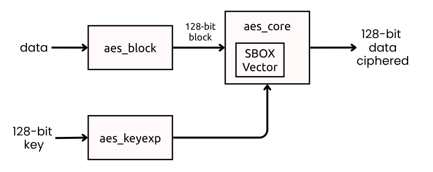
In aes_core_ecb.v, the 128-bit input block is mapped in column-major order into state bytes (a00, a10, a20, a30, then next column). This ordering must match your test vectors and software packing, otherwise encryption looks “wrong” even if round logic is correct.
In this project, input words are first assembled in aes_block.v from a 32-bit AXI4-Stream input:
case (word_count)
  2'd0: block_accum[127:96] <= s_axis_tdata;
  2'd1: block_accum[95:64]  <= s_axis_tdata;
  2'd2: block_accum[63:32]  <= s_axis_tdata;
  2'd3: block_accum[31:0]   <= s_axis_tdata;
endcase
So four 32-bit words become one AES block.
Padding behavior in aes_block.v
Because ECB works on full blocks, aes_block.v applies PKCS#7 when s_axis_tlast arrives and the current block is incomplete. The logic handles 1, 2, or 3 missing words and appends the corresponding repeated padding byte values.
It also handles the full-block PKCS#7 case by emitting an extra 0x10 block when the message ends exactly on a block boundary:
if (pad_after_full) begin
  m_axis_tdata <= 128'h10101010101010101010101010101010;
  m_axis_tvalid <= 1'b1;
end
That is correct PKCS#7 behavior and avoids ambiguity when decrypting padded ECB data.
AES key expansion
AES key expansion transforms the original user key into the round keys consumed by AddRoundKey at each encryption stage. In AES-128, the 128-bit input key is expanded into 11 round keys (k0 to k10). This is implemented in aes_keyexp_128.v, which keeps the current expanded key as four 32-bit words and updates them every clock cycle according to the selected round.
The transformation combines RotWord, SubWord, and Rcon with the XOR recurrence that defines the AES schedule. In practical RTL terms, the last word is first rotated by one byte, each byte is substituted with the AES S-box, and then XORed with the round constant. From that transformed value, the rest of the new key words are generated through chained XOR operations with the previous words.
The S-box in this module is implemented as a constant lookup vector, the same nonlinear substitution table used conceptually in SubBytes. Rcon is also preloaded as a vector of 32-bit values indexed by round, where only the most significant byte carries the finite-field round constant. This keeps the datapath simple and deterministic in synthesis.
In this implementation, key expansion is registered, so timing alignment with the ECB core matters. The core requests round keys with the round signal and uses an alignment cycle so rkey is stable when each AES round executes.
/* key expansion algorithm */
always @(posedge aclk) begin
  if (!resetn || round == 0) begin
    wr0 <= key[127:96];
    wr1 <= key[95:64];
    wr2 <= key[63:32];
    wr3 <= key[31:0];
  end
  else begin
    wr0 <= w3rs ^ rcon ^ w0;
    wr1 <= w3rs ^ rcon ^ wr0 ^ w1;
    wr2 <= w3rs ^ rcon ^ wr0 ^ w1 ^ w2;
    wr3 <= w3rs ^ rcon ^ wr0 ^ w1 ^ w2 ^ w3;
  end
end
AES Electronic Codebook (ECB) mode
ECB encrypts each plaintext block independently:
\[C_i = AES_K(P_i)\]Its main advantage is simplicity. The downside is that equal plaintext blocks produce equal ciphertext blocks, leaking patterns. So ECB is good as a learning and verification baseline, but not a strong general-purpose mode for real data protection.
ECB core in this project
The file aes_core_ecb.v implements the AES-128 round flow. First, the core applies SubBytes, where every byte of the state is transformed through the AES S-box lookup table. This is the nonlinear step that gives AES most of its confusion properties. Then it applies ShiftRows, which rotates each row of the state matrix with different offsets to spread byte influence across columns.
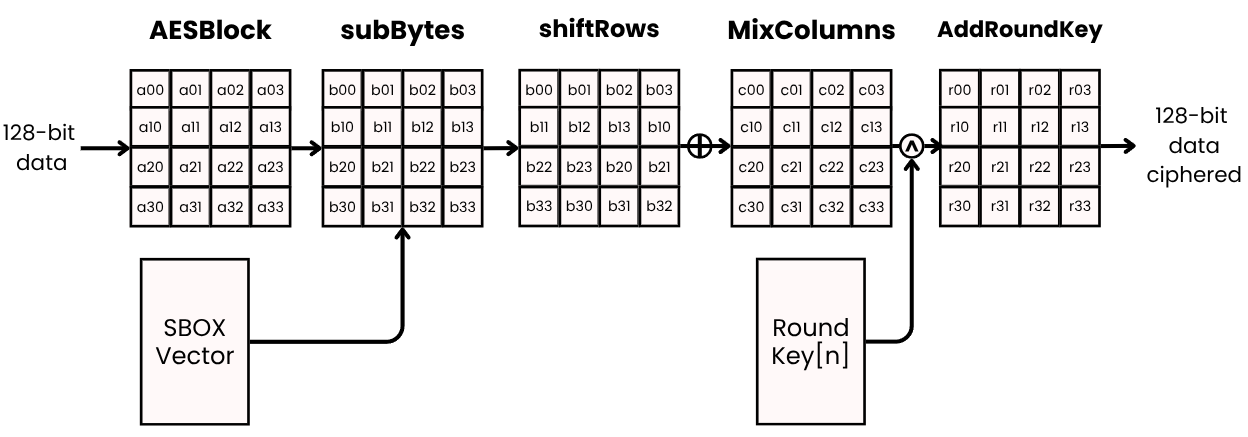
After that, for rounds 1 to 9, the core performs MixColumns, where each column is multiplied in GF(2^8). In this implementation, that arithmetic is built using helper functions like mul2 and mul3. Finally, each round closes with AddRoundKey, where the current state is XORed with the round key generated by aes_keyexp_128.v.
In round 0, the core only performs AddRoundKey over the input state. In the last round, MixColumns is skipped as required by the AES specification.
The AddRoundKey selection changes based on round number:
assign ark00 = ((round_use == 0) ? (a00[7:0] ^ rk00) :
               (round_use == LAST_ROUND) ? (sr00 ^ rk00) :
               (mc00 ^ rk00));
This single expression encodes the initial round (no SubBytes/ShiftRows/MixColumns before XOR), middle rounds, and final round (without MixColumns).
ECB control/data timing view
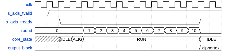
The diagram shows the practical handshake interpretation in this implementation: input is accepted when s_axis_tready=1, the core becomes busy during round processing, and output becomes valid when the core returns to ready.
The entire AES-128 encryption of one block takes 12 cycles in this design: 1 cycle to latch input, 1 cycle to align round keys, then 10 cycles for the rounds. This is a common latency for a non-pipelined AES core.
AES Counter (CTR) mode
In the ECB mode, each block is encrypted independently, which can leak patterns, for example, if we want to encrypt an image, and this image contains a white background, the pattern of the white background would be visible in the ciphertext. The solution to this is using a method able of eliminate the independency between blocks. One of these methods is CTR mode.
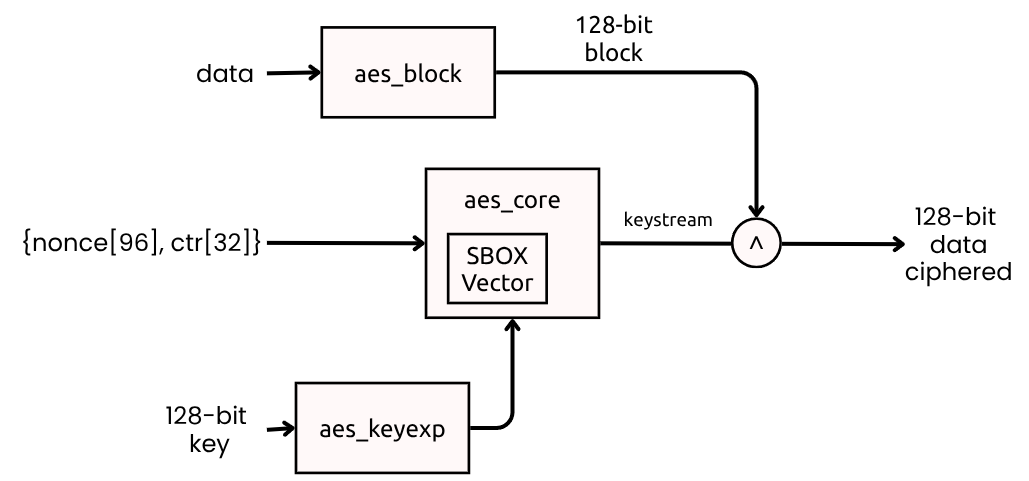
The CTR mode uses a unique counter value for each block to produce a keystream, which is then XORed with the plaintext.
It works with 128-bit blocks like, ecb, but since this time what we are going to encrypt is the counter, and we are not going to use a 128-bit counter, we can use an “small” 32-bit counter, and concatenate it with a nonce to create the 128-bit input for AES.
This way, the final AES input is {nonce[95:0], ctr_counter[31:0]}, and the encryption formula is:
In addition, since the next values of the counter are known, the keystream can be precomputed, allowing for parallel encryption of blocks and eliminating the block-pattern issue of ECB.
aes_ctr_wrapper.v architecture
I’ve created a wrapper module aes_ctr_wrapper.v that reuses aes_core_ecb as a keystream generator. The wrapper:
- Latches
s_axis_tdata,s_axis_tkeep, ands_axis_tlast - Builds
{nonce[95:0], ctr_counter[31:0]}as AES input - Waits for AES completion
- XORs plaintext and keystream with byte masking (
tkeep) - Forwards output and metadata, then increments counter
The byte-masked XOR is implemented with xor_with_tkeep so partial blocks are naturally supported without PKCS#7 in CTR path.
Conclusion
FPGAs are a strong platform for cryptographic acceleration because they map well to deterministic bit-level operations, allow explicit control of latency and throughput, and can scale from compact single-core implementations to parallel engines.
This AES RTL, in the same way as SHA256, is very modular: block packing (aes_block), key expansion (aes_keyexp_128), block cipher core (aes_core_ecb), and operation-mode wrapper (aes_ctr_wrapper). That separation makes integration easier and enables focused optimization. For example, you can pipeline rounds, replicate CTR lanes, or evolve key schedule support to AES-192/256 without rewriting the whole subsystem.
In the last DEFCON conference, I talked about the role of FPGAs in modern cybersecurity, especially with the future quantum attacks, and as more I investigate about these implementations, more I am convinced that FPGAs will be a key part of our future cybersecurity landscape, both as a tool for defense and as a potential attack vector. Understanding how to implement and verify cryptographic primitives in hardware is essential for anyone interested in this field.
Next week I’ll be at the RootedCON conference, and I will be giving a talk about this topic, and why we must integrate now FPGAs in HSM.
The code of this article is uploaded to Github.