Getting Started with the SCU35 and Spartan Ultrascale+
 xilinx,
devices,
tools,
workflow
xilinx,
devices,
tools,
workflow
 SCU35
SCU35
Spartan UltraScale+ has been officially released, and AMD has provided a development board to help engineers get familiar with this device. The board is called the SCU35.
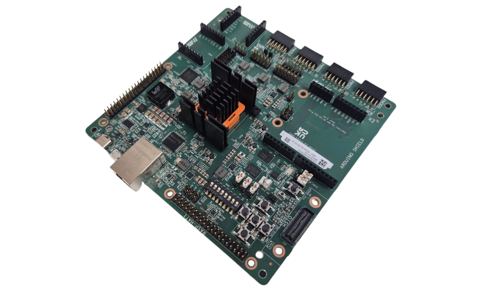
This board features the SU35P, which includes 36k logic cells, 48 DSP slices, and almost 2MB of memory. Furthermore, the board is designed as I prefer: a development board with many peripherals and interfaces, allowing us to connect various devices.
In this article, we will use this board with one of its included peripherals: the power monitor. This system is based on two INA700 I2C power monitors, which monitor the 5V rail and the 0.85V rail. Specifically, we are going to read the 5V rail, as it is the main rail of the board.
Table of Contents
- Hardware design
- Exporting the hardware
- Vitis HW platform creation
- Vitis application creation
- Debugging the application
Hardware design
Let’s start by creating the hardware project for the board. The SCU35 has been included in Vitis 2025.1, so you will need to update to this version to work with this kit.
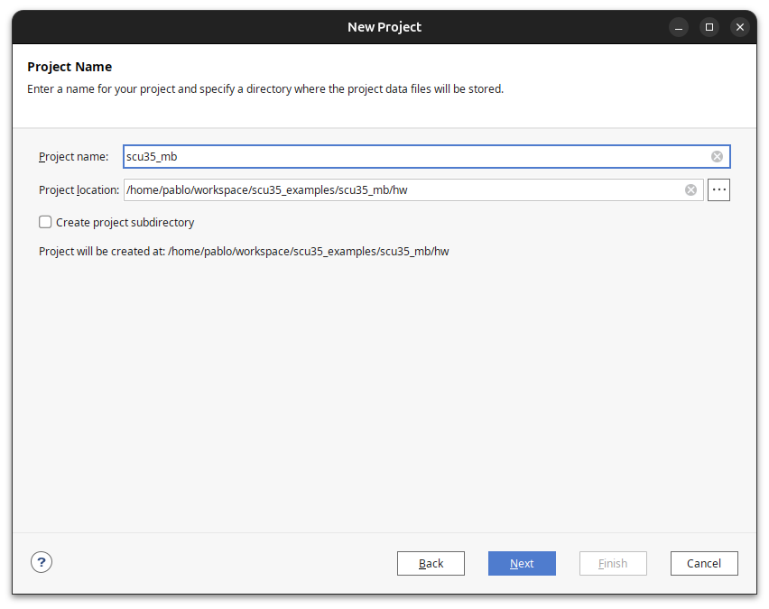
In my case, my project is named scu35_mb. I created a folder for the project, and then a /hw subfolder where the Vivado project is located.
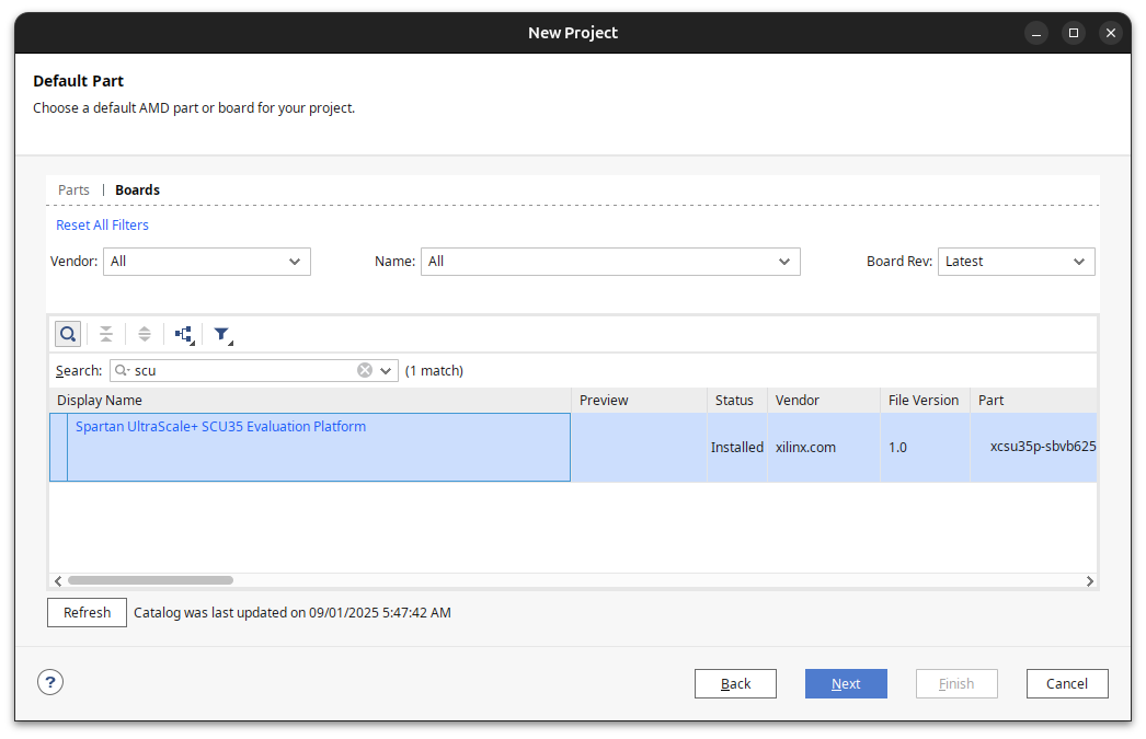
Select the SCU35 board from the Vivado board list to easily access all the board’s peripherals, such as the two INA700 devices.
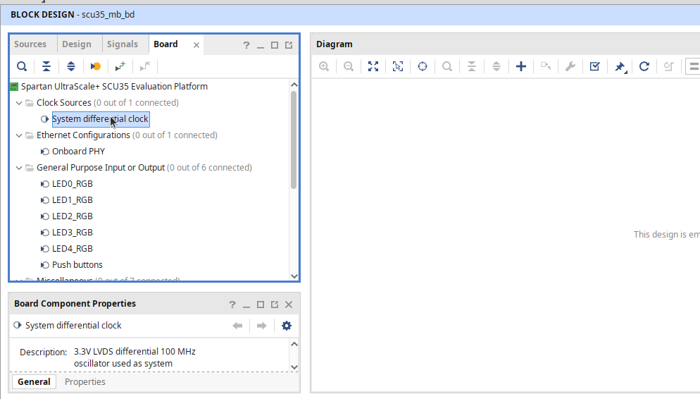
Once the project is created, we will work on the Block Design. Create a new block design with the same name as the project, adding the suffix _bd.
In the block design, navigate to the Board tab. First, add the System differential clock.
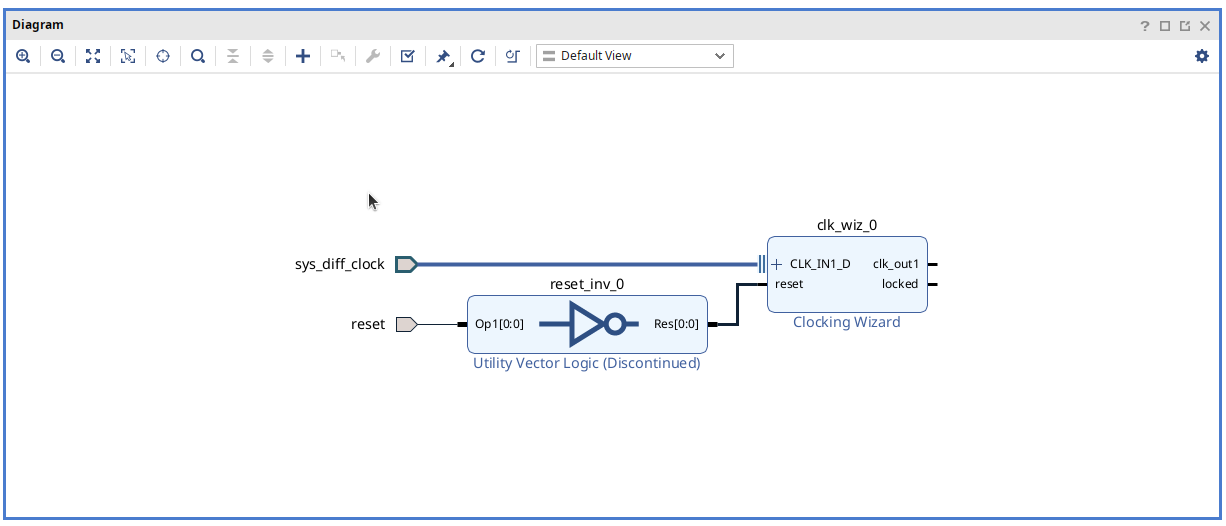
After adding the clock wizard, use Vivado’s Run Connection Automation to add the reset signal. Avoid using the reset from board components, as it may add a non-negated reset.
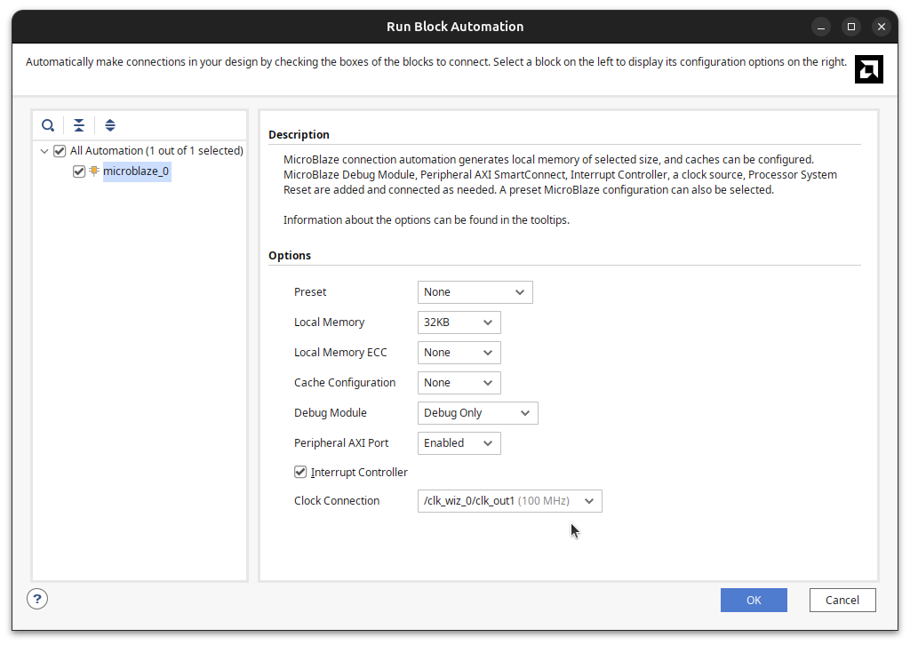
Now, add the Microblaze processor and configure it according to your needs. For this application, the microcontroller preset and 32/64KB of local memory are sufficient. Ensure that the Debug Module is enabled to allow debugging of your application. Also, enable the Interrupt Controller, as it is required for the AXI Ethernet Lite IP, which needs interrupts to work efficiently.
Finally, ensure that the clock used for the microcontroller is the one created earlier.
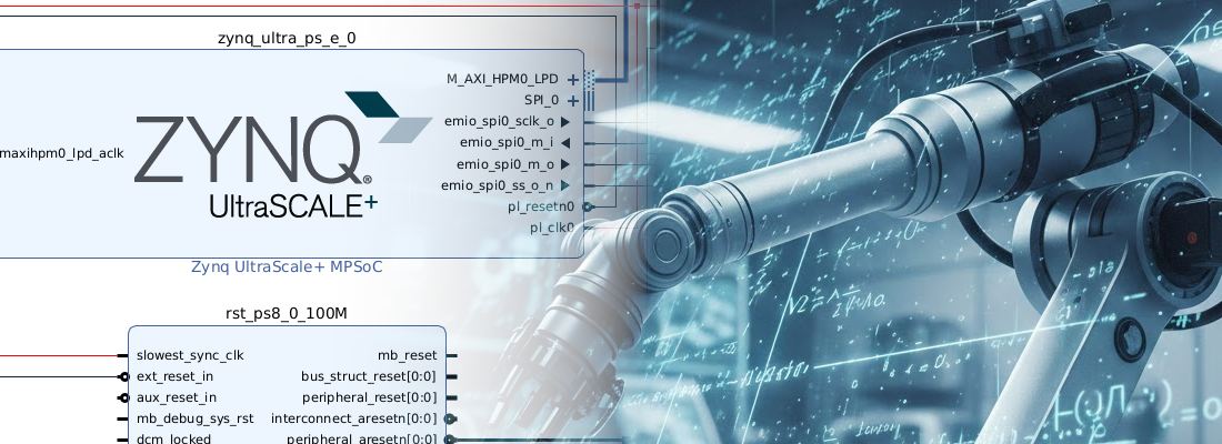
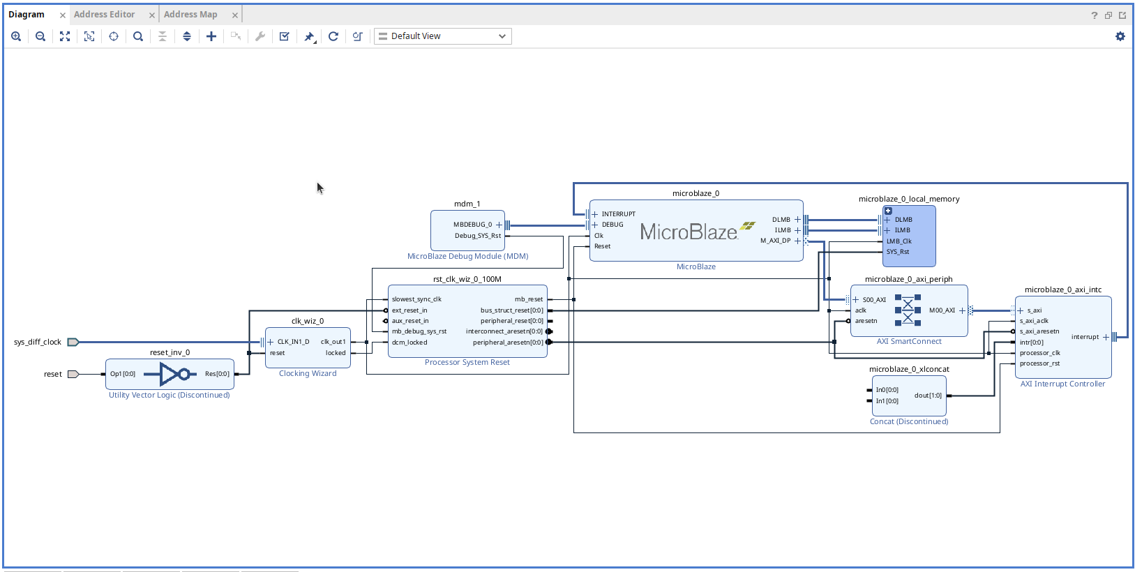
Once this is done and Vivado has made all the connections, the block design will look like the following. You can see that elements such as the interrupt controller and the reset system have been added to the design.
The external reset of the Processor System Reset IP may be unconnected, so you can connect it to the external reset input, at the output of the inverter.
At this point, we have added all the IPs needed to make Microblaze work. Now, we will add some extra peripherals to access the board’s features.
Again, in the Board tab, add:
- LED0-3_RGB, which will be connected to two AXI GPIO IPs.
- IIC INA, which will add an AXI IIC.
- UARTB, which will be connected to an AXI UART LITE.
- Onboard PHY, which will be connected to an AXI EthernetLite IP.
Once all these peripherals have been added, let Vivado make all the connections. The resulting block design will look like this:
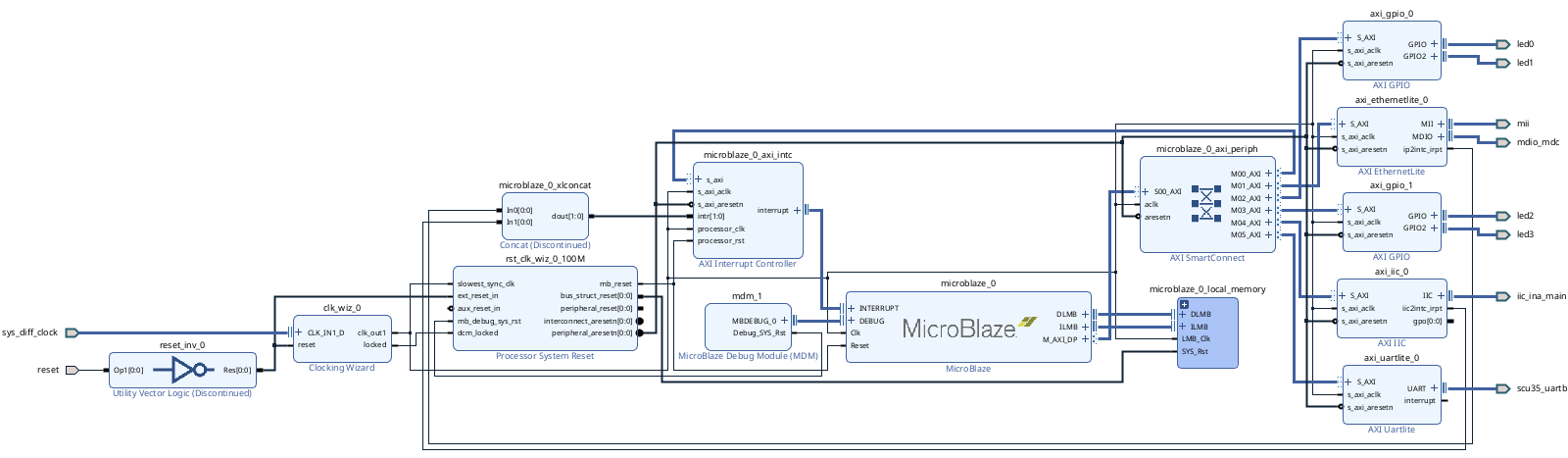
Now, finalize the block design by connecting interrupts for Ethernet Lite and INA I2C.
Exporting the hardware
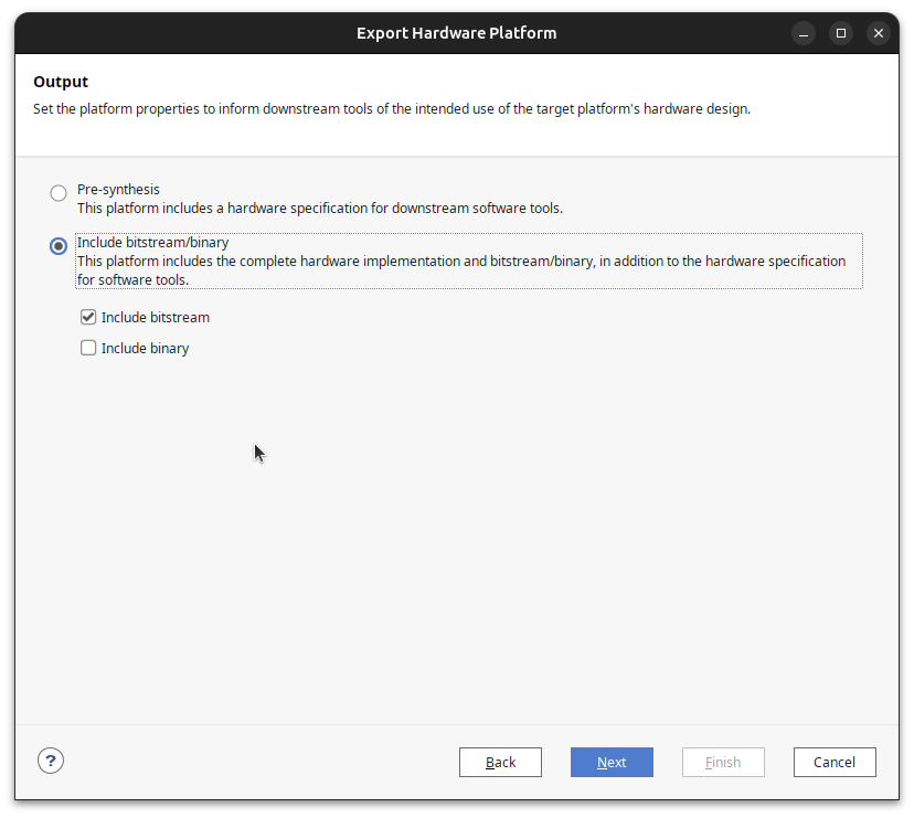
When the block design is complete, click on Generate Device Image to generate the .pdi file. You will notice that the Bitstream option has disappeared for Spartan UltraScale+, because these devices feature the Platform Management Controller, which manages the FPGA boot process. The .pdi file also contains its configuration.
Once your design is complete and the .pdi file is generated, export the hardware from Vivado for use in Vitis.
Vitis HW platform creation
The Vitis workflow starts with platform creation. The platform contains all the configurations and libraries needed to manage the peripherals added to the block design.
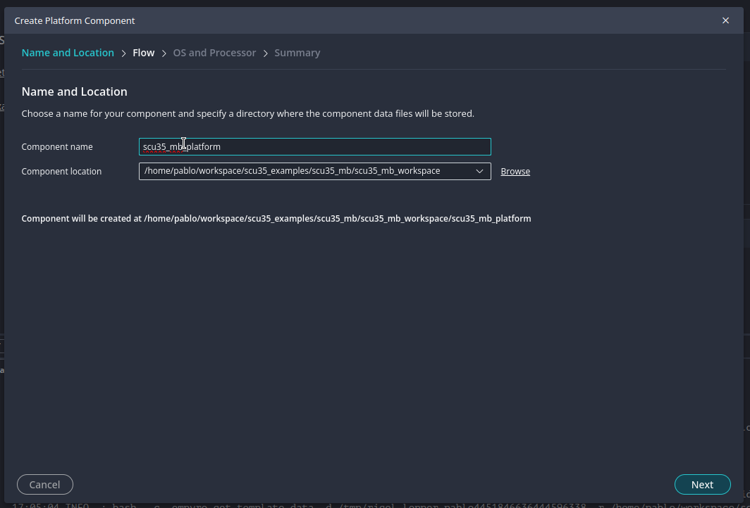
To create the platform project, first create or select the Vitis workspace, and click on Create Platform Component.
Then, choose a name for the platform and select the .xsa generated in Vivado to link this platform to your hardware design.
Once the platform is created, for this project you don’t need to add anything new to the BSP, so you can just build the platform.
Vitis application creation
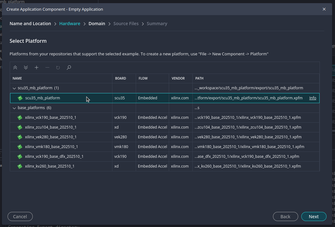
When the platform is ready, you can start creating applications for it. Click on Create Embedded Application, select a name, and choose the platform you just created to tell Vitis that this application will run on this hardware.
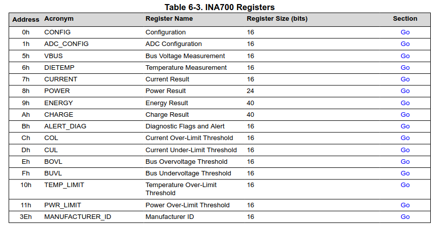
Now, it’s time to write your code. The INA700 is an I2C power monitor, so you will need the list of the device’s registers. The figure below is extracted from the datasheet, showing the addresses to read voltage (5h), current (7h), and power (8h).
Once you know where to read, you need to know the conversion between the value you read and the actual magnitude. Again, this information can be found in the datasheet.
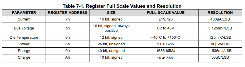
With this information, you can now write your code.
In the code I created, there is a generic function named i2c_read_n that reads n bytes from the I2C bus. Then, using this function, in the loop we sequentially read the three magnitudes.
Note that voltage and current are 16-bit variables, but power is a 24-bit variable.
/**
* @file scu35_power_monitor.c
* @brief Power monitoring application for SCU35 using INA700 sensor and Microblaze.
*
* This application reads voltage, current, and power values from the INA700 sensor
* via I2C, converts the raw register values to engineering units, and prints the results
* over UART using xil_printf.
*
* @author P.Trujillo
* @date 2025-09-28
*/
#include "xparameters.h"
#include "xil_printf.h"
#include "xiic.h"
#include "xstatus.h"
#include <stdint.h>
#include <string.h>
/* I2C device and INA700 sensor definitions */
#define IIC_DEV_ID XPAR_AXI_IIC_0_BASEADDR // I2C device base address
#define INA700_I2C_ADDR 0x44U // INA700 I2C address
/* INA700 register addresses */
#define REG_VBUS 0x05U // VBUS voltage register (16-bit, 3.125 mV/LSB)
#define REG_CURRENT 0x07U // Current register (16-bit signed, 480 uA/LSB)
#define REG_POWER 0x08U // Power register (24-bit, 96 uW/LSB)
/* INA700 conversion factors */
#define VBUS_LSB_V (3.125e-3f) // VBUS LSB in volts
#define CURR_LSB_A (480e-6f) // Current LSB in amps
#define POWR_LSB_W (96e-6f) // Power LSB in watts
static XIic Iic; // I2C instance
/**
* @brief Reads n bytes from a register over I2C.
*
* Sends the register address and reads nbytes from the INA700 sensor.
*
* @param i2c_addr I2C address of the device.
* @param reg Register address to read from.
* @param buf Buffer to store the read data.
* @param nbytes Number of bytes to read.
* @return XST_SUCCESS if successful, XST_FAILURE otherwise.
*/
static int i2c_read_n(u8 i2c_addr, u8 reg, u8 *buf, int nbytes)
{
// Send register address
int sent = XIic_Send(Iic.BaseAddress, i2c_addr, ®, 1, XIIC_STOP);
if (sent != 1) return XST_FAILURE;
// Read nbytes from the device
int recv = XIic_Recv(Iic.BaseAddress, i2c_addr, buf, nbytes, XIIC_STOP);
return (recv == nbytes) ? XST_SUCCESS : XST_FAILURE;
}
int main(void)
{
XIic_Config *Cfg;
int Status;
u8 i2c_buff[3] // Buffer for I2C data
u16 vbus_raw = 0; // Raw VBUS register value
u16 curr_raw = 0; // Raw current register value
uint32_t pwr_raw24 = 0; // Raw power register value (24-bit)
float vbus_V; // VBUS in volts
float current_A; // Current in amps
float power_W; // Power in watts
int32_t vbus_mV; // VBUS in millivolts
int32_t current_mA; // Current in milliamps
int32_t power_mW; // Power in milliwatts
int16_t curr_s16; // Signed current value
// Lookup I2C configuration
Cfg = XIic_LookupConfig(IIC_DEV_ID);
if (!Cfg) { xil_printf("IIC: LookupConfig failed\r\n"); return XST_FAILURE; }
// Initialize I2C peripheral
Status = XIic_CfgInitialize(&Iic, Cfg, Cfg->BaseAddress);
if (Status != XST_SUCCESS) { xil_printf("IIC: CfgInitialize=%d\r\n", Status); return Status; }
// Set I2C address for INA700
XIic_SetAddress(&Iic, XII_ADDR_TO_SEND_TYPE, INA700_I2C_ADDR);
// Start I2C peripheral
Status = XIic_Start(&Iic);
if (Status != XST_SUCCESS) { xil_printf("IIC: Start=%d\r\n", Status); return Status; }
xil_printf("SCU35 Power Monitor\r\n", INA700_I2C_ADDR);
while (1) {
/* Read VBUS register (16-bit) */
Status = i2c_read_n(INA700_I2C_ADDR, REG_VBUS, i2c_buff, 2);
if (Status != XST_SUCCESS) { xil_printf("I2C VBUS fail\r\n"); continue; }
vbus_raw = ((u16)i2c_buff[0] << 8) | i2c_buff[1];
/* Read CURRENT register (16-bit signed) */
Status = i2c_read_n(INA700_I2C_ADDR, REG_CURRENT, i2c_buff, 2);
if (Status != XST_SUCCESS) { xil_printf("I2C CURRENT fail\r\n"); continue; }
curr_raw = ((u16)i2c_buff[0] << 8) | i2c_buff[1];
curr_s16 = (int16_t)curr_raw;
/* Read POWER register (24-bit unsigned) */
Status = i2c_read_n(INA700_I2C_ADDR, REG_POWER, i2c_buff, 3);
if (Status != XST_SUCCESS) { xil_printf("I2C POWER fail\r\n"); continue; }
pwr_raw24 = ((uint32_t)i2c_buff[0] << 16) | ((uint32_t)i2c_buff[1] << 8) | i2c_buff[2];
/* Convert raw values to engineering units */
vbus_V = vbus_raw * VBUS_LSB_V; // Convert VBUS to volts
current_A = curr_s16 * CURR_LSB_A; // Convert current to amps
power_W = pwr_raw24 * POWR_LSB_W; // Convert power to watts
vbus_mV = (int32_t) (vbus_V * 1000); // VBUS in millivolts
current_mA = (int32_t) (current_A * 1000); // Current in milliamps
power_mW = (int32_t) (power_W * 1000); // Power in milliwatts
/* Print results (xil_printf does not support floats) */
xil_printf("VBUS=%d mV I=%d mA P=%d mW "
"(raw: V=0x%04X I=0x%04X P=0x%06lX)\r\n",
vbus_mV, current_mA, power_mW,
vbus_raw, curr_raw, (unsigned long)pwr_raw24);
/* Simple delay loop */
for (volatile uint32_t d = 0; d < 5U*100000U; ++d);
}
}
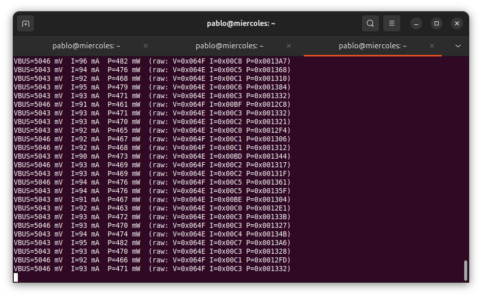
Finally, all the values are sent over the UART interface. Notice that the value sent is multiplied by 1000 to display mV, mA, and mW. This is because the xil_printf function does not support printing floating-point values.
Debugging the application
When the code is ready, you can debug the application from Vitis.
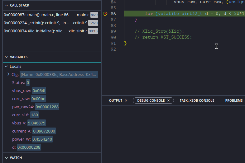
If you add a breakpoint after all the measurements have been read, you can expand the Locals view to see the value of all local variables and check if they are correct.
Finally, from the host PC, you will receive the measurements continuously.
This simple project was developed to get familiar with the board, but it allows us to check the power consumed by the FPGA. Adding sensors like the INA700 to the FPGA can be useful for monitoring input voltage in real time and, in case of an incorrect reading, switching your application to a safe state.
Also, I mentioned the Platform Management Controller, which is one of the most interesting updates in these devices. We will explore it in future articles.