Getting started with the MPFS Discovery Kit
 microchip,
polarfire soc,
tools
microchip,
polarfire soc,
tools
 MPFS Discovery Kit
When the MPFS Discovery Kit was released, I thought that this board was what the Icicle Kit was supposed to be. A small board, with enough interfaces, even a MIPI interface for high-speed communications, Ethernet, SD Card, LEDS, Buttons… and the best, USB powered. The PolarFire part used in this board is the MPFS095T, smaller than the one used in the Icicle kit but still featuring 5 RISC-V processors inside. In this article, we are going to create a base design for this board using the PolarFire SoC Microprocessor Subsystem (MSS) with the latest Libero 2024.
First of all, we are going to create a new project in Libero 2024. In my case the project name will be mpfs_discovery_base.

Now, we need to configure the part that is based on the MPFS Discovery Kit. The par is a PolarFireSoC MPFS095T with the package FCSG325.

For this kind of part, we also need to define the core voltage and the default I/O technology. For the MPFS Discovery Kit, the configuration is the next.

Once the project is created, unlike for AMD devices, where the SoC is configured inside the Vivado, for Microchip parts we need to open another application, the PolarFire MSS Configurator. This application is installed with Libero and can be accessed in Linus using the next command.
pablo@miercoles:~$ /media/pablo/ext_ssd0/microchip_v2024.1/Libero_SoC_v2024.1/Libero/bin64/pfsoc_mss
Since we are using a development board, many configurations of the MSS depend on how the board is designed, for example, which GPIO are used, or which UART interface is connected to the FTDI chip. To have a base configuration for the MPFS Discovery kit, we can navigate to the GitHub repository for the Kit, and navigate to the script_support folder. In this folder, we can find the file MPFS_DISCOVERY_KIT_MSS.cfg, which can be opened with the PolarFire MSS Configurator.
Once the file is opened, we can see all the peripherals, FIC configurations, Clocks and memories configured for the Kit. In the first tab we can find the peripherals available in the MPFS Discovery Kit.

Since we are not going to use all the peripherals in this example, we can disable most of them, especially the ones that are connected to the fabric. Disabling these peripherals, we will get a smaller block. For this kit, we can find that the peripheral MMUART_0 is connected to the fabric, so the block will have two ports for the TXD and the RXD pins.

However, the MMUART1 is connected to the dedicated MSS pins.

This is pretty similar to the AMD SOCS when a PS peripheral is connected to the MIO (MSS Bank), or to the EMIO (PL).

Also, since we are not going to use the FIC interfaces, we can disable them.

For the rest of the configurations, since they configure the clocks and the DDR / cache memories, the best is to keep them without modifications. Finally, we can generate the MSS block.

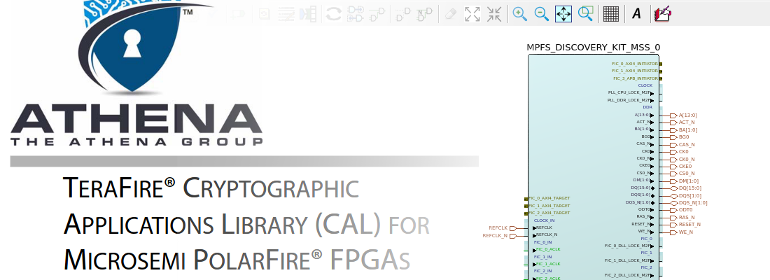
Coming back to Libero, we need to import the MSS generated. We can do this navigating to Create Design > Import MSS, and selecting the .cxz file. This file is in reality a zip file with all the tcl and verilog files to generate the block. When the MSS is imported, in the Components tab will appear the MPFS_DISCOVERY_KIT_MSS.
Next, we are going to create a SmartDesign.

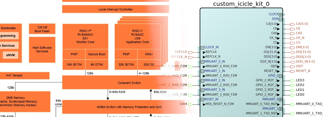
In the SpartDesign, we can drag and drop the MSS component to add it to the design.

You can notice that, although there are peripherals that are connected to the MSS pins, they appear in the SmartDesign but they are connected to a dedicated ports. For the GPIO, we have disabled all of them except the range 0-6, to connect them to the LEDs.

To be able of using the LEDs, we need to add the constraints file. In the same Github repository, you can find the constraints folder. We are going to add all of them, except the CCC.pdc to the project. And also, we are going to add the file fic_clocks.sdc to the project.
With all these files added to the project, we can now open the MPFS_DISCOVERY_KIT_BOARD_MISC.pdc, where are declared the LEDs outputs.
set_io -port_name LED1 \
    -pin_name T18 \
    -fixed true \
    -DIRECTION OUTPUT

set_io -port_name LED2 \
    -pin_name V17 \
    -fixed true \
    -DIRECTION OUTPUT

set_io -port_name LED3 \
    -pin_name U20 \
    -fixed true \
    -DIRECTION OUTPUT

set_io -port_name LED4 \
    -pin_name U21 \
    -fixed true \
    -DIRECTION OUTPUT

set_io -port_name LED5 \
    -pin_name AA18 \
    -fixed true \
    -DIRECTION OUTPUT

set_io -port_name LED6 \
    -pin_name V16 \
    -fixed true \
    -DIRECTION OUTPUT

set_io -port_name LED7 \
    -pin_name U15 \
    -fixed true \
    -DIRECTION OUTPUT
To connect the LEDS to the MSS, we need first to promote the corresponding pin to the Top level.

And then, change the name of the port to LED1, LED2…

At this point, maybe some reset pins of the MSS are disconnected. To avoid warning and errors, we can connect the negated input resets to VCC, by Tying them high, and marking the unconnected outputs as Unused.
With all the steps completed, we can generate the component and Set as Top the component of the SmartDesign.
Now, we can Synthesize the design and later, connect the board and execute all the steps until RUN Program Action. In my case, I am using Ubuntu, so I have to run a local license server, even for the Silver license. At the moment of synthesis, I don’t know why but seems that Synplify, the synthesizer used by Libero, cannot connect to the license server, reporting this error.
License server system does not support this version of this feature.
Feature:       synplifypro_actel
License path:  1702@localhost:
FlexNet Licensing error:-25,234
A workaround I have used is to kill the license server and rerun it.
At this point, the HW design is programmed into the MPFS Discovery kit, so now, it’s time for the SW development.
For the SW development, we need to open SoftConsole. In my case, I am using the latest version which is the 2022.2. The interface is based on the Eclipse, and I guess that the new one will be based on Eclipse Theia, like everyone now.

To create a SW project, again, we are going to use the Github Repository, in this case the PolarFire SOC bare Metal examples. With this repository cloned, we can import one of the projects to SoftConsole.

When the project is imported, we can change the Debug configuration to auto-configure all the project to be used with the MPFS Discovery Kit. The configuration I used is LIM-Debbug-DiscoveryKit.

When we change the configuration, we can find that all the includes of the project changed to the ones of the Discovery kit.

The example I ran was the GPIO Interrupt, which sends over UART some strings. In this case, the UART I have connected in the kit is the UART conencted to the processor u54_1, so the output I received is from this processor.

I received this board almost a month ago, and I had some issues with the Flash Pro Express application trying to program the reference kit. However, using a custom design, and using LIbero to program the board, all went quite well. As I mentioned before, for me, the MPFS discovery kit should have been the first kit released with the PolarFire, it is small, USB powered, has many interfaces, Linux capable, all of this with a cost of 120 $. I noticed that the package they used in this board for the PolarFire SOC is really small, making the heat dissipation so poor, and making the device reach high, but I guess safe, temperatures. Now, it is time to make this board run Linux, but this will be after the summer holidays.